Setting Up a Raspberry Pi Web Server

I've been using a Raspberry Pi as a low-cost/low-power server for the past couple years. This post is my short collection of notes related to setting up a Pi as a web server with the classic "LAMP" stack (Linux, Apache, MySQL, PHP.)

Software

Raspbian https://www.raspberrypi.org/downloads/raspbian/
Win32DiskImager https://sourceforge.net/projects/win32diskimager/
TeraTerm https://ttssh2.osdn.jp/index.html.en
Swish-SFTP http://www.swish-sftp.org/

Prepare an SD Card

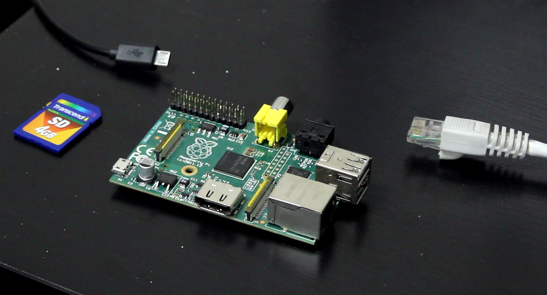
Unzip the Raspbian archive and use Win32DiskImager to write the .img to an SD card. To run Win32DiskImager, you might to Right Click -> Run as Administrator. When the write completes, place the SD card in the Pi and plug in ethernet and micro USB cables. There is no need for a keyboard, mouse or monitor.

Connect to the Pi via SSH

Use your router to figure out the Pi's IP address and optionally setup the router to assign the Pi a static IP address. Run TeraTerm and start a SSH connection to that IP address. The default username is "pi" and the default password is "raspberry".

Optionally change the hostname by replacing all instances of "raspberrypi" with a new hostname:

sudo nano /etc/hostname sudo nano /etc/hosts

Optionally change the username by replacing all instances of "pi" with a new username:

sudo -s nano /etc/passwd (change the username AND home dir) nano /etc/shadow nano /etc/group nano /etc/gshadow nano /etc/sudoers mv /home/pi /home/newusername passwd newusername shutdown -r now

Reopen TeraTerm and login with the new username and password.

Configure Raspbian and Install Software Updates

Run raspi-config to setup the OS:

sudo raspi-config Expand the filesystem Set boot options to "B1 Console" Optionally set internationalization options to "en_US" and set the timezone Finish and let it reboot

Install software updates:

sudo apt-get update sudo apt-get upgrade

Install and Configure Apache, MySQL and PHP

Install the web server software:

sudo apt-get install apache2 php5 mysql-server mysql-client sudo chown -R yourusername /var/www sudo chgrp -R yourusername /var/www ln -s /var/www/html ~/html

At this point it's all up and running. Going to the Pi's IP address in a web browser should reveal the default Apache page. That page is stored in /var/www/html/index.html, and also accessable through the link you made as ~/html/index.html. Assuming you want the web server to be public, you probably want to setup port forwarding on your router (TCP port 80) and use a domain name and dynamic DNS service so people can type in a .com instead of an IP that might change over time.

I use Google Domains. It's around $12/year for a .com and they include dynamic DNS service at no extra cost. Here's how to setup the dynamic DNS service they offer:

Login to https://domains.google.com/ In the rows of domain names, click on the DNS icon for the domain you want to setup In the Synthetic Records section, select Dynamic DNS For the subdomain, use "@" (without the quotes) for no subdomain (like when someones goes to yourdomain.com instead of www.yourdomain.com) Then make another record for the "www" (without quotes) subdomain Click on the > icon next to each record, then click View Credentials

You can use software like ddclient to notify Google when your IP changes, or you can keep things simple and just visit a specially-crafted URL periodically to keep Google up-to-date. I wrote a simple script to visit that URL and record it's response to a text file. Be sure to make the script executable:

nano ~/dns_update_script.sh wget https://username:password@domains.google.com/nic/update?hostname=yourdomain.com -qO dns_update_results.txt wget https://username:password@domains.google.com/nic/update?hostname=www.yourdomain.com -qO- >> dns_update_results.txt echo " Last run: `date`" >> dns_update_results.txt chmod +x ~/dns_update_script.sh

The script downloads the web pages to the text file (the first wget creates the text file, the second wget appends to the text file) and then I also append the current date and time to the text file.

Setup a cron job to run the script at the start of every hour:

crontab -e 0 * * * * ~/dns_update_script.sh

Using Virtual Hosts to Serve Multiple Domains

A single computer can serve multiple domains. Apache supports this and calls it a "Virtual Host." You can repeat the following steps for as many domains as needed:

sudo nano /etc/apache2/sites-available/yourdomain.conf <VirtualHost *:80> ServerName www.yourdomain.com ServerAlias yourdomain.com *.yourdomain.com DocumentRoot /var/www/yourdomain </VirtualHost> sudo mkdir /var/www/yourdomain sudo chown -R yourusername /var/www/yourdomain sudo chgrp -R yourusername /var/www/yourdomain ln -s /var/www/yourdomain ~/yourdomain sudo a2ensite yourdomain sudo service apache2 reload

Using Swish-SFTP to Copy Files to the Pi

After installing Swish-SFTP, there will be a "Swish" device listed in File Explorer > This PC. Double-click it, then choose "Add SFTP Connection" near the top of the window. After making a connection you can drag-and-drop files between Windows and the Pi.

That's it. You now have a web server that requires less than 5 watts of power to run, and occupies hardly any space in your home.

YouTube Video

I also made a YouTube video showing the process. In the video I did not cover Virtual Hosts.

FTDI SPI Tutorial: LibMPSSE with Visual Studio 2015

FTDI is mostly known for their USB UART chips, but some of their higher-end ICs also have an “MPSSE” (multi-protocol synchronous serial engine) that can do SPI, I2C and JTAG. I made a YouTube video tutorial covering the basics of their SPI library for C. I thought I'd also write this post to summarize that video and provide its content in text form for easier referencing.

FTDI sells a ready-made USB adapter, it's part number C232HM-DDHSL-0. You can buy it from the usual suppliers (Mouser, DigiKey, etc.) for around $26 + shipping. It's essentially an FT232H broken out to 10 wires with female 0.1” connectors.

Some Useful Links

http://www.ftdichip.com/Products/Cables/USBMPSSE.htm
The product page for this USB adapter and some other ones.

http://www.ftdichip.com/Drivers/D2XX.htm
The D2XX driver you'll need to install. Windows will automatically install the VCP driver (UART driver) when you plug the cable in, but you need to manually install this D2XX driver if you want to use the cable for SPI/I2C/JTAG projects.

http://www.ftdichip.com/Support/Documents/DataSheets/Cables/DS_C232HM_MPSSE_CABLE.PDF
The datasheet for this USB adapter. It's got the schematic, a brief summary of what's possible, and tells you which color wire is used for what.

http://www.ftdichip.com/Support/Documents/AppNotes/AN_188_C232HM_MPSSE_Cable_in_USB_to_SPI-Interface.pdf
An App Note that provides a HelloWorld-level demo of their SPI library for C. It's a useful document, but their code isn't as clear as I'd like. They also did things the hard way (declaring a bunch of function pointers for the DLL) which is not needed if you will be using Visual Studio.

http://www.ftdichip.com/Support/Documents/AppNotes/AN_178_User_Guide_For_LibMPSSE-SPI.pdf
The User Guide for their SPI library for C. It documents all of the functions and data structures.

http://www.ftdichip.com/Support/SoftwareExamples/MPSSE/LibMPSSE-SPI/LibMPSSE-SPI.zip
The actual library and a simple demo project. This ZIP file contains the headers and the .lib file you will need to copy into your project.

Prepare a Visual Studio 2015 Project

  1. Open Visual Studio 2015, then create a new project:
    File > New > Project Templates > Visual C++ > Win32 Console Application Give the project a name, then click OK In the Application Wizard: click Next, then uncheck "Precomiled Header", then click Finish
  2. Remove some unneeded files from the project: stdafx.h, targetver.h, and stdafx.cpp
    In the Solution Explorer, right-click over each of those files > Remove > Delete
  3. Copy four files from FTDI's LibMPSSE-SPI zip file (linked above) into the Visual Studio project: ftd2xx.h, libMPSSE.lib, libMPSSE_spi.h, and WinTypes.h
    Those files are in LibMPSSE-SPI.zip > LibMPSSE-SPI > Release > samples > SPI > SPI Copy those four files into your Visual Studio project's folder. By default, that would be in: This PC > Documents > Visual Studio > Projects > YourProjectName > YourProjectName
  4. Tell Visual Studio about those four recently added files:
    In the Solution Explorer, right-click on Header Files > Add > Existing Item Select ftd2xx.h, libMPSSE_spi.h, and WinTypes.h, then click Add In the Solution Explorer, right-click on Resource Files > Add > Existing Item Select linMPSSE.lib, then click Add
  5. Fix an error in WinTypes.h: Replace "sys/time.h" with "time.h"
    Change line 5: Before: #include <sys/time.h> After: #include <time.h>

Minimalist Demo Program

By now the Visual Studio project is fully setup. You can starting using the API. Below is a simple demo program I wrote. It's communicates with an SPI gyroscope and displays X/Y/Z velocities on screen.

  1. The program starts by displaying information about each MPSSE "channel" that is available. An MPSSE channel is the part of the IC that can do SPI/I2C/JTAG protocols. Some FTDI ICs are UART-only, so they won't have any MPSSE channels. The USB adapter I'm using has one MPSSE channel. Some of their more advanced ICs have two MPSSE channels.
  2. The user will be asked to specify which MPSSE channel to use.
  3. The program will prepare that channel for SPI Mode 0 with a 1 MHz clock.
  4. The SPI gyro will be configured by writing to five of it's registers.
  5. Finally, an infinite loop is used to poll the gyro's X/Y/Z velocity registers. Those velocities are formatted and printed to the screen.
  6. The program can be closed by pressing Ctrl-C.
There are 1 channels available. Channel number: 0 Description: C232HM-DDHSL-0 Serial Number: 1637980 Enter a channel number to use: 0 x = -182, y = -395, z = -1157 x = -50, y = -14, z = -276 x = -351, y = -159, z = -1936 x = -211, y = -293, z = -190 x = -217, y = -310, z = -200 x = -232, y = -329, z = -177 x = -216, y = -301, z = -185 x = -239, y = -329, z = -167 x = -211, y = -304, z = -185 x = -215, y = -307, z = -209 x = -234, y = -285, z = -189 ...

Source Code

// red wire = 3v3 // black wire = ground // orange wire = sclk // yellow wire = mosi // green wire = miso // brown wire = cs #include <stdio.h> #include <Windows.h> #include "libMPSSE_spi.h" // a helper function for showing fatal error messages void print_and_quit(char cstring[]) { printf("%s\n", cstring); getc(stdin); exit(1); } int main(int argc, char **argv) { Init_libMPSSE(); FT_STATUS status; FT_DEVICE_LIST_INFO_NODE channelInfo; FT_HANDLE handle; // check how many MPSSE channels are available uint32 channelCount = 0; status = SPI_GetNumChannels(&channelCount); if (status != FT_OK) print_and_quit("Error while checking the number of available MPSSE channels."); else if (channelCount < 1) print_and_quit("Error: no MPSSE channels are available."); printf("There are %d channels available.\n\n", channelCount); // print out details for each MPSSE channel for (int i = 0; i < channelCount; i++) { status = SPI_GetChannelInfo(i, &channelInfo); if (status != FT_OK) print_and_quit("Error while getting details for an MPSSE channel."); printf("Channel number: %d\n", i); printf("Description: %s\n", channelInfo.Description); printf("Serial Number: %d\n", channelInfo.SerialNumber); } // ask the user to select a channel uint32 channel = 0; printf("\nEnter a channel number to use: "); scanf_s("%d", &channel); // open the MPSSE channel (get the handle for it) status = SPI_OpenChannel(channel, &handle); if (status != FT_OK) print_and_quit("Error while opening the MPSSE channel."); // init the channel (configure it) ChannelConfig channelConfig; channelConfig.ClockRate = 1000000; // 1 MHz channelConfig.configOptions = SPI_CONFIG_OPTION_MODE0 | SPI_CONFIG_OPTION_CS_DBUS3 | SPI_CONFIG_OPTION_CS_ACTIVELOW; channelConfig.LatencyTimer = 75; status = SPI_InitChannel(handle, &channelConfig); if (status != FT_OK) print_and_quit("Error while initializing the MPSSE channel."); // configure the gyro uint8 tx_buffer[6] = { 0x20 | (1 << 6) | (0 << 7), // first register is 0x20, bit6 high for auto-increment mode, bit7 low for write mode 0b01111111, // value for register 0x20 0b00101001, // value for register 0x21 0b00001000, // value for register 0x22 0, // value for register 0x23 0 // value for register 0x24 }; uint32 transferCount = 0; uint32 options = SPI_TRANSFER_OPTIONS_SIZE_IN_BYTES | SPI_TRANSFER_OPTIONS_CHIPSELECT_ENABLE | SPI_TRANSFER_OPTIONS_CHIPSELECT_DISABLE; status = SPI_Write(handle, tx_buffer, 6, &transferCount, options); if (status != FT_OK) print_and_quit("Error while configuring the gyro."); // enter an infinite loop that reads X/Y/Z velocities from the gyro while (1) { uint8 tx_buffer[7] = { 0x28 | (1 << 6) | (1 << 7), // first register is 0x28, bit6 high for auto-increment mode, bit7 high for read mode 0, // read register 0x28 0, // read register 0x29 0, // read register 0x2A 0, // read register 0x2B 0, // read register 0x2C 0 // read register 0x2D }; uint8 rx_buffer[7] = { 0 }; uint32 transferCount = 0; uint32 options = SPI_TRANSFER_OPTIONS_SIZE_IN_BYTES | SPI_TRANSFER_OPTIONS_CHIPSELECT_ENABLE | SPI_TRANSFER_OPTIONS_CHIPSELECT_DISABLE; status = SPI_ReadWrite(handle, rx_buffer, tx_buffer, 7, &transferCount, options); if (status != FT_OK) print_and_quit("Error while reading from the gyro."); int16 x = (rx_buffer[2] << 8) | rx_buffer[1]; int16 y = (rx_buffer[4] << 8) | rx_buffer[3]; int16 z = (rx_buffer[6] << 8) | rx_buffer[5]; printf("x = %+6d, y = %+6d, z = %+6d\n", x, y, z); } // this code will never be reached due to the infinite loop above, but you would normally want to end with this: Cleanup_libMPSSE(); return 0; }

YouTube Video

Servo Tester / 2.4GHz Spectrum Analyzer / Tetris Firmware

As promised in my previous post about this servo tester / spectrum analyzer / tetris implementation, I have uploaded the source code to my Servo Tester repository on GitHub. Check out the photos in that previous post if you'd like to see the work as it progressed over a few months of code refactoring and feature additions. I made a brief video clip to demonstrate the features of the firmware:

RS232 Telemetry Viewer

While developing my balancing robot I needed to visualize certain variables. Being able to monitor angles, velocities and feedback loop factors made it easier to tune the control loop and verify the correct functioning of my sensors. I wrote the program in Java, utilizing the Swing and RXTX libraries.

Current values for each data point are shown with the sliders and text labels. Clicking on a data point will bring up a new window that shows the history of that data point in the form of a line graph. Multiple line graph windows can be used to track the history of several items at once.

The source code can be downloaded as a zip file, or accessed through my RS232 Telemetry Viewer repository on GitHub. To run the code you will need to install the RXTX library.

The code is split into eight classes: Main, Database, TelemetryGUI, ConfigurationLoader, SerialConfigPanel, SerialPortListener, BallPanel and LineGraph. The TelemetryGUI class has two inner classes: TelemetryGroup and TelemetryItem.

Main simply creates an instance of the Database and TelemetryGUI classes.

Database is used to store the history of values for each data point.

TelemetryGUI configures the main window and creates an instance of the ConfigurationLoader to read the configuration text file and make the corresponding panels. A BallPanel is used to visualize the robot's pitch and yaw angles. A SerialConfigPanel shows the available serial ports and baud rates, and allows the user to establish a connection with the selected port.

SerialPortListener is used to spawn a new thread that monitors the RS232 link, interprets incoming text, and populates the database with new values.

LineGraph is a window that shows the recent history of an item in the form of a constantly updating line graph.

Here's a video clip of me testing an early version of this program with my robot back in December 2013:

Balancing Robot Firmware

I'm releasing the firmware for my balancing robot into the public domain. Use it however you wish. The code is rather specific to my choice in microcontroller and sensors, but it might still be helpful to those working on their own robots.

Most of the work takes place in two files: main.c and isrs.c.

The main() function does all of the initialization work, then enters an infinite loop that constantly streams telemetry data out via RS232.

The interrupt service routines in isrs.c are where all of the “real work” is done. That's where the new values from all sensors are read, steering and throttle commands are received from the CC2500-based 2.4GHz transmitter, and the motor PWM values are adjusted based on a PID control loop.

I have amassed a small collection of reusable code while working on various projects with the STM32F0 microcontroller. This collection of code is not polished enough for sharing, but since it was used in this project I am including it anyway. It's in the /f0lib/ directory and should be used with caution. Be sure to read the function implementations before reusing the code in your own projects. The code in /f0lib/ was only written with my particular use cases in mind.

The firmware can be downloaded as a zip file, or accessed through my Balancing Robot repository on GitHub. Have fun!

Video clips and more photos are in my previous post from May 18th.

< Prev  3  Next >